
 One of the limitations of computer mapping technology is that it is new. There is little historical imagery and data available as a result, although this has started to change. The integration of paper and imaged maps into computer mapping technology is possible, and this tutorial will walk through the process of georeferencing.
Georeferencing is the process of placing an image into two dimensional space. In essence, georeferencing pins a scanned map to particular geographical coordinates.
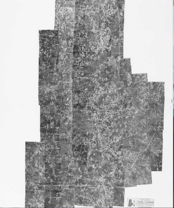
This tutorial will georeference a map of Durham County from 1955. In addition to the scanned map, we will use two current layers as referents: the Durham roads layer, and the Durham county boundary. Note that because the layers are more recent than the historical map, many roads will not exist in the image. Georeferencing historical imagery requires familiarity with geographic characteristics and changes.
 Step 1: Enable Georeferencing
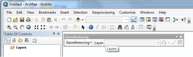
First, under the “Customize” Menu Bar option, navigate to “Toolbar” and select Georeferencing. The figure to the right displays the Georeferencing toolbar.
Step 2: Add Data and Image Layers
 Next, add the shapefiles that you will use as referents for the image.
Once this is done, add the image to be georeferenced. Note that you will almost certainly not see that image, as it lacks spatial coordinates. However, the image will appear in the Table of Contents.
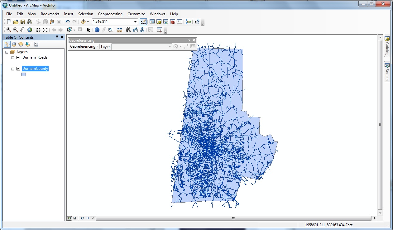
In this example, I have added Durham County (blue polygon) and the Durham roads layer (blue lines).
 Step 3: Fitting the Image to the Layers
The next step will relocate the image to the center of your current window and will expand the image only to the point where the entire image is visible. In this case, Durham County is taller than it is wide, so vertical space will be maximized.
First, it is a good idea to zoom, if necessary, so that your current view roughly matches where the image will be place. In this case, zooming to the full extent of the Durham county boundary will accomplish this.
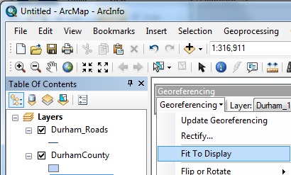
 Second, under the Georeferencing toolbar, click “Georeferencing” and select “Fit to Display.” The image should be roughly aligned to the data layers, though if not, this is not problematic.
As you can see from the image to the right, there is some distance between the county boundaries of today (red lines) to the hand-drawn county boundaries located in the image (white lines).
 Step 4: Adjusting the Map
ArcGIS georeferences images through the addition of control points. The control points tool (to the right) operates through two mouse clicks: the first mouse click selects a point on the image, and the second mouse click pins that point to a location within a data layer.
 For example, in the image to the right, I have selected a major intersection that likely has not changed in the last 60 years. After my first click, where I’ve selected a point near the top of the intersection, a green crosshair is placed. As I move the mouse, ArcGIS will pin my current crosshair to a proximate layer, in this case, the Durham roads layer.
Once you click a second time, the map will move to conform to the new control points. Control points work in combination, so as you add new control points, your image will (ideally) match more closely to your referents.
There is a limit to how much each subsequent control point will improve fit as more points are added. Generally, it’s a good idea to zoom in to improve accuracy and to create control points across the extent of the image.
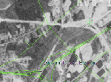
 After about 15 control points, we can compare the image to the included shapefiles. As you can see, if we assume that major roads have not changed, the green lines correspond well to the image, while the county boundary does to a lesser extent.
Step 5: Statistics and Transformations
Before saving the results, it is also a good idea to evaluate the results. Open the Table of Points to see each of your control points and the root mean squared error of all control points.
The Root Mean Square error (RMS) provides a rough guide to how consistent your control points are to one another with reference to the map. Note that a low value does not mean that you’ve necessarily georeferenced the image well, it means you’ve georeferenced consistently. High RMS errors indicate that your control points are less consistent with one another in comparison with a low RMS error. One way to address this issue is to identify especially probelmatic control points and either replace or remove these points. However, always reevaluate how well your image maps to the referent shapefiles.
 You may delete control points or add new points at this stage. In addition, you may also try different transformations, although second- or third-order transformations are rarely needed.
Step 6: Saving the Results
Under the Georeferencing tab of the Georeferencing toolbar, select “Update Georeferencing.” Spatial information is saved in two new files that MUST accompany the image, an “.aux” file and a “.thw” file.
General Tips
– Zoom close to the layer resolution in order to improve accuracy
– Use more than 1 referent if possible. In this example, the county boundary provided a rough guide with respect to how far off the image initially is, but was not used to actually georeference the image.
– Georeference to accurate features. In this example, the county boundary was hand-drawn on the image and is not as precise as photographed features, like roads.